|
| |
TM 5-5430-210-12
2-11.
Berm Construction, 50,000-Gallon
(189,250-Liter) Tank. The following instructions
are for a 26-foot by 66-foot (7.924-meter x
20.117-meter) (flat dimensions).
NOTE
A minimum of three-foot (one-meter)
working clearance is necessary between
the side of the tank and the berm on all
four sides.
a. Clear and level an area 30 feet by 70 feet
(9.14 meters x 21.34 meters).
b. Inspect area closely. Remove all sharp objects
from the leveled area.
c. Slope all four sides of the leveled area in to-
ward the center (fig. 2-15). The center should be no
more than nine inches (22.86 centimeters) below
ground level. If possible, provide a sand bottom ap-
proximately four inches (10.16 centimeters) thick.
d. Erect a four-foot (1.22-meter) high
berm around the outside of the sloped area.
earth
e. To provide a berm drain, place a 2-inch
(5.08-centimeter) pipe with a gate valve through
the bottom of the discharge end of the berm in
order to provide a means of draining accumulated
water. Valve should be normally closed; open valve
only to drain water from the bermed area.
M a k e c e r t a i n t h a t t h e v a l v e i s
c l o s e d a n d l o c k e d a f t e r
i n s t a l l a t i o n . I n v e n t o f t a n k
rupture, an open valve would permit
fuel to drain from berm and could
cause fire or explosion.
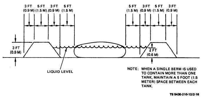
2-12. Typical Berm Cross Section. Figure 2-16
shows a cross section view with dimensions of a
typical berm.
Figure 2-16. Typical Berm Cross Section.
Section II. MOVEMENT TO A NEW WORKSITE
2-13. General. Whenever possible, prior to move-
purged of all residual fuel and fumes and cleaned
ment, unit assemblies should be disassembled,
and preserved for future use.
2-16
Change 5
|