Order this information in Print

Order this information on CD-ROM

Download in PDF Format


Click here to make tpub.com your Home Page

Page Title: Installation of Filler and Discharge Hoses
Back | Up | Next

Click here for a printable version

Google


Web
www.tpub.com

Home


Information Categories
.... Administration
Advancement
Aerographer
Automotive
Aviation
Combat
Construction
Diving
Draftsman
Engineering
Electronics
Food and Cooking
Math
Medical
Music
Nuclear Fundamentals
Photography
Religion
USMC
   
Products
  Educational CD-ROM's
Printed Manuals
Downloadable Books


TM   5-5430-210-12 2-8. Installation of Filler and Discharge Hoses. 
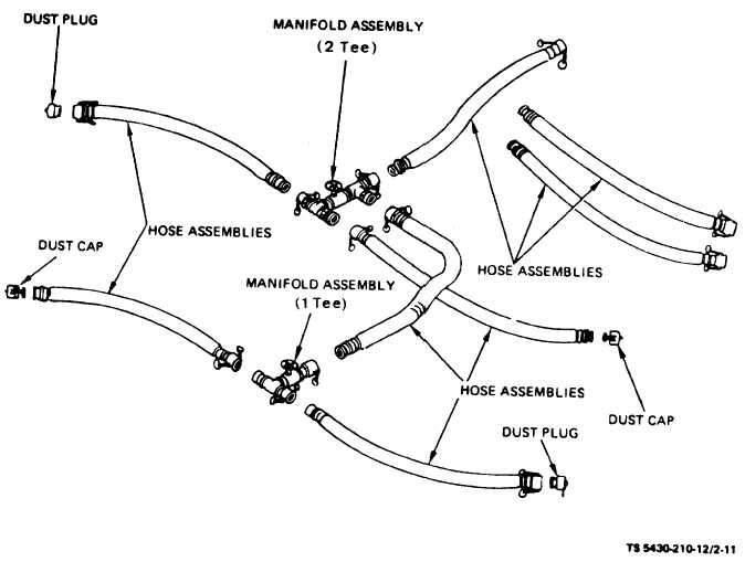
b. The filler and discharge hose assemblies (fig. (Tanks, NSN 5430-00-052-3412 and NSN 5430-00- 1-9)  are  fitted  with  quick  disconnect  female  cou- 641-8552). plings on one end and quick disconnect male adapt- a. Remove   the   4-inch   (10.16-centimeter)   dust ers  on  the  other  end.  Place  the  female  coupler  on  the cap from the elbow (fig. 2-5) which will be used for male adapter end of the filler discharge elbow (fig. filling. 2-5) and depress the coupler cam-lever arms locking the hose assembly in place, A typical hose manifold is shown in figure 2-11. Figure   2-11   Typical   Hose   Manifolding   (10,000   Gallon   Tank) 2-10 Change 2

Privacy Statement - Press Release - Copyright Information. - Contact Us - Support Integrated Publishing

Integrated Publishing, Inc. - A (SDVOSB) Service Disabled Veteran Owned Small Business