|
| |
TM 5-4930-234-13&P
7.
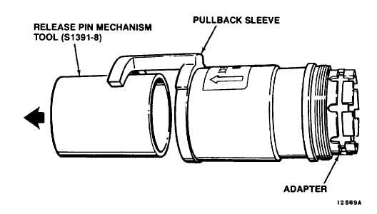
Slide adapter (43) and release pin mechanism tool, S1391-8, inside pullback sleeve (34). End of
adapter (43) should extend beyond end of pullback sleeve (34).
8.
Hold end of adapter (43) and pull release pin mechanism tool, S1391-8, out of pullback sleeve (34). See
Figure 5-12.
9.
Insert six latches (39) in slots of adapter (43). Thread nose sleeve (38) onto pullback sleeve (34) until
handtight.
10.
Lightly lubricate pressure regulator seals (46 and 47), and o-ring (45).
11.
Install small pressure regulator seal (47) in groove at back of body (49). Webbed side must face toward
handle end.
12.
Install large pressure regulator seal (46) in second groove from outlet end of body (49). Webbed side
must face outlet end.
13.
Install o-ring (45) in outlet end of body (49).
14.
Install body (49) in vise jaws, S1391-15, and clamp in vise. See Figure 5-13.
15.
Insert pressure regulator spring (36) in pressure regulator sleeve (35). Install both parts inside body
(49).
16.
Install regulating positioning tool, S1391-9, in body (49) as follows. See Figure 5-14.
Figure 5-12. Removal of Release Pin Mechanism Tool
Change 3 5-20
|