|
| |
TM 5-4320-313-14
2-2.
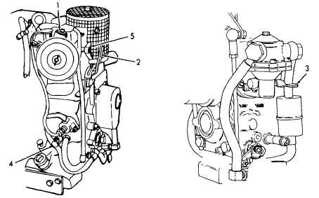
PUMPING ASSEMBLY CONTROLS AND INDICATORS. (Refer to
figure 2-1 and table 2-1).
Table 2-1. Operator's Controls and Indicator
CONTROL, INDICATOR
KEY
OR CONTROL
FUNCTION
1 Air Filter Indicator
Indicates a dirty air filter element. A red
band appears in window, which indicates element
needs replacing. Air filter indicator must be
reset after servicing of the air filter.
2 Throttle Control Hand Lever Controls engine speed. With the hand lever in
START position, the engine is at its highest
operating speed. Place the lever between START
and STOP, to obtain the desired engine speed.
3 Fuel Primer Lever
Mechanically connected to fuel lift pump. Used
to prime engine by forcing fuel from fuel tank
into fuel system.
4 Extra Fuel Button
Provides more fuel to engine during starting.
Pulling button out allows more fuel to engine.
Button returns to normal position when engine
reaches operating speed.
5 Decompression Lever
Controls engine compression. Lever is placed
in decompression position during engine start-
ing and returns to compression when engine
reaches operating speed.
Figure 2-1. Operator's Controls and Indicator.
2-2
|

