|
| |
TM 5-4320-306-24
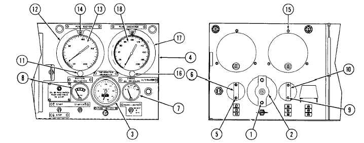
2-16. REPLACE/REPAIR CONTROL PANEL ASSEMBLY (Continued)
11
Remove nuts and lockwashers (1 ) from back of tachometer/hourmeter mounting bracket (2).
12
Remove mounting bracket (2).
13
Carefully slide TACHOMETER/HOURMETER (3) out through front of control panel (4).
14
Remove nuts and lockwashers (5) from back of oil pressure indicator mounting bracket (6).
15
Remove oil pressure indicator mounting bracket (6).
16
Tag and remove wires from ENGINE OIL PRESSURE indicator (7).
17
Carefully slide indicator out through front of control panel (4).
18
Tag and remove wires from BATTERY VOLTMETER (8).
19
Remove nuts and lockwashers (9) from battery voltmeter mounting bracket (10).
20
Remove mounting bracket (10).
21
Carefully remove BATTERY VOLTMETER (8) through front of control panel (4).
22
Remove thumbscrew (11) and bezel (12) securing compound gage (PUMP SUCTION) (13) to front of control
panel (4).
23
Remove screws (14) and nuts and lockwashers (15).
24
Carefully remove compound gage (13) through front of control panel (4).
25
Remove thumbscrew (16) securing pressure gage (PUMP DISCHARGE) (18) and bezel (17) to front of control
panel (4).
2-55
|