|
| |
TM 5-4320-305-24
4-7. REPLACE/REPAIR VALVES, VALVE GUIDES, AND VALVE SEATS (Continued)
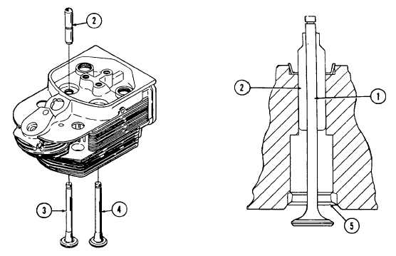
8 Measure valve stem (1)/valve guide (2) clearance on inlet valve (3) and exhaust valve (4) with micro feeler gage. The
inlet valve stem/valve guide clearance limit is 0.0118 inch (0.3 mm). The exhaust valve stem/guide clearance limit is
0.0197 inch (0.5 mm).
9 Clean valve seat insert rings (5) with small wire bristle brush and diesel fuel oil and dry with low pressure compressed
air. Inspect and replace for excessive wear, pitting, cracking, or improper valve seat insert ring angle (greater or less
than 45 degrees).
NOTE
Valve seat insert rings can be inspected and cleaned without
being removed from the cylinder head.
Always use NEW valve in making valve seat insert ring
measurements.
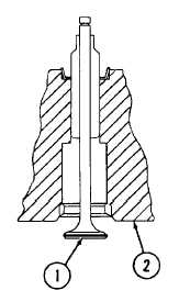
10 Measure distance between installed valve head center (1) and cylinder
head seat (2) with depth gage. Distance should be between 0.2283
and 0,2520 inch (5.8 and 6.4 mm).
4-50
|