|
| |
TM 5-4320-305-24
4-4. REPAIR INJECTION PUMP (Continued)
c. Remove housing from vat.
d. Relieve air pressure. Disconnect air pressure sourceand remove 1/4-28 'connector from port. Remove 1/4-28
pipe plug from other port.
e. Remove aluminum stock from ledge.
f. Remove six pistons (56) using plunger pliers KDEP 2915.
g. If any defects were indicated in steps a or b, remove and discard defective parts. Install new parts and repeat
steps 8 through 11 to inspect for defects.
h. If no defects were indicated in steps a or b, continue to step 12 below.
12 Install three jaws (67), three jaws (66), and three screws (65).
13 Install rod (64) into housing.
14 Position rod (64) at center of travel. Install screw (63) using torque wrench. Torque screw to 44 to 52 in-lb (59.7 to
70.5 N-m).
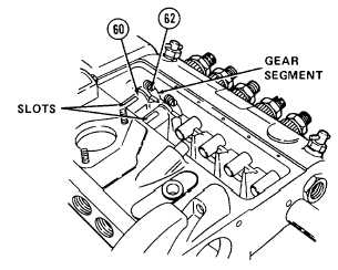
15 Place together the following parts tagged during disassembly as belonging to bore number one: gear ring (61),
control sleeve (60), and screw (62).
a. Install screw (62) onto gear ring (61) but do not tighten.
b. Place gear ring (61) onto control sleeve (60).
c. Position gear ring so that adjusting slot of control sleeve faces out and screw is on the right hand side.
d. Slide control sleeve (60) onto plunger (74) of appropriate bore.
e. Mesh gear teeth of gear ring (61) onto gear teeth of rod (64).
f.
Rotate control sleeve (60) to face outward as shown. If
control sleeve and gear ring are the original parts,
aline
scribe marks made during disassembly.
g. Tighten screw (62) to 26 to 28 in-lb (2.9 to 3.2 N.m).
4-21
|