|
| |
TM 5-4320-305-24
3-18.
REPAIR ALTERNATOR, V-BELT PULLEY, AND FAN (Continued)
c.
Connect the multimeter test probes to each of the following pairs of test points.
Point A to Point A
Point B to Point B
Point C to Point C
d.
The test should indicate a resistance of 1.0 ohm between each of the three pairs of test points. If any one test
fails, replace the stator.
3
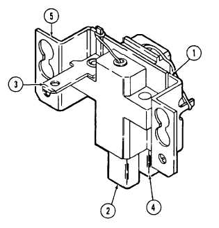
Test brush assembly (1) using a multimeter set to
ohms.
a.
Connect the multimeter between each of the
following pairs of points.
Brush (2) and terminal (3)
Brush (4) and holder (5)
b.
There should be continuity between both pairs of
points.
c.
Connect the multimeter between each of the
following pairs of points.
Brush (2) and holder (5)
Terminal (3) and holder (5)
d.
There should be infinite resistance between both
pairs of points. If any one test fails, replace
brush assembly.
4
Test rotor using a multimeter set to ohms.
a.
Place test leads across the slip rings. Resistance should read between 11 to 14 ohms.
b.
Place one test lead to a slip ring and the other to the rotor body. Resistance should read infinite.
c.
Place one test lead on other slip ring and second test lead to rotor body. Resistance should read infinite.
d.
If any one test fails, replace rotor.
3-92
|