|
| |
TM 5-4320-305-24
2-31. TEST/REPLACE SOLENOID VALVE(Continued)
TEST/INSPECTION:
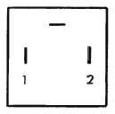
1 Electrically test operation of solenoid valve. Connect pin (P2) to
ground. Intermittently apply +12 vdc to pin 1 (P1). The valve should
normally be open with +12 volts applied to pin 1 (P1) but should
close when no voltage is applied to pin 1 (P1). These signals
simulate the engine fault sensitive control signals from the control
panel. Test valve is open when an electrical signal (+12 vdc) is
applied to the valve solenoid pin 1 (P1), simulating the reset signal.
If either malfunctions, replace solenoid valve.
2 Inspect solenoid valve and bolt for damage, rust, corrosion, or restrictions in fuel flow. If damaged, severely
rusted, or corroded, replace valve and/or bolt.
3 Inspect electrical contacts on both ends of electrical connectors at solenoid valve. Inspect wiring to and from
control panel. For connections at control panel, follow procedures in paragraphs 2-15 and 2-16. If any electrical
problems or malfunctions exist, replace wiring and/or connectors as necessary.
INSTALLATION:
1 Install solenoid valve (7) using bolt and new washers (6). Rotate clockwise and tighten securely.
CAUTION
Do not force electrical connector onto solenoid valve. Be careful to match slots in connector to
plug prongs on solenoid valve.
2 Install three-slot square electrical connector (5) onto three-prong plug on solenoid valve (17).
3 Install screw (4).
4 Install fuel filter-to-injection pump hose (3) with bolt (1) and new washers (2). Tighten bolt securely.
5 Bleed air from fuel lines in accordance with paragraph 2-42.
2-119
|