|
| |
TM 5-4320-305-10
2-6.
OPERATING PROCEDURE (Continued)
(4)
Open needle valve (4) of the air valve cover assembly.
(5)
Be certain discharge check valve (5) is closed.
(6)
Remove control panel cover assembly and turn four brass valves to the open position.
d.
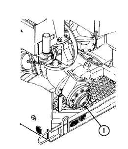
Discharge hose installation. Aline the discharge hose exactly with the piping of the discharge manifold
assembly before connecting it to the pump. Never try to pull the hose into place by tightening the coupling.
(1)
Connect
the
discharge
hose
to
victaulic coupling flange (outlet) (1) of
the discharge manifold assembly.
(2)
Be sure that discharge hose is free of
twists
and
pinch
points
after
installation. Support and secure
discharge hose to avoid strain and
vibration during operation.
(3)
Make certain that all connections are
tight.
e.
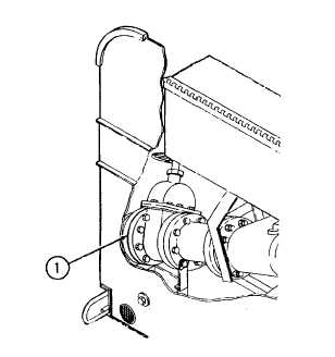
Suction hose installation. Aline the suction hose exactly with the piping of the suction assembly before
connecting it to the pump. Never try to pull the hose into place by tightening the coupling.
(1)
Connect the suction hose to the
victaulic coupling flange (inlet) (1) of
the suction assembly.
(2)
Be sure that the suction hose is free of
twists
and
pinch
points
after
installation. Support and secure
suction hose to avoid strain and
vibration during operation. Highest
point in the suction hose should be at
the pump.
(3)
Make certain that all connections are
tight. Even a slight leak in the suction
line will affect priming, head, and
capacity.
Change 1 2-69
|


