|
| |
TM 5-4320-305-10
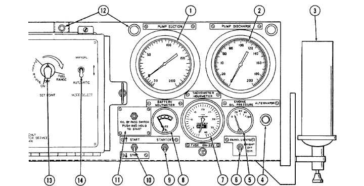
Table 2-1. Operator’s Controls and Indicators - Continued
KEY
CONNECTOR
FUNCTION
9
STARTER switch
Starts engine. When pushed to the STARTER position,
allows electric current to flow to the starter motor.
This switch is spring loaded to return to the down
position when released.
10
START/STOP switch
Energizes and deenergizes the pump and engine control
and operating circuits. This switch must be in the
START position before pressing the STARTER switch.
11
OIL BYPASS switch
Bypasses the low oil pressure switch. When starting
the engine, there is no oil pressure in the lubrication
system, and the low oil pressure switch would
automatically shut down the engine. Pressing the OIL
BYPASS switch allows the oil pressure to reach operating
pressure during starting. This switch must be
pressed before pressing the STARTER switch, and held
in during starting.
12
Panel lights
Illuminate when turned on with PANEL LIGHTS
switch (6). Can be set to bright or dim.
13
SET POINT switch
Used to adjust engine speed and pump discharge
pressure.
2-3
|

