 |
|||
|
|
|||
|
Page Title:
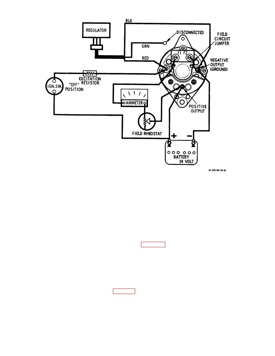
Figure 4-28. Field current draw test setup. |
|
||
| ||||||||||
|
|
 Figure 4-28. Field current draw test setup.
resistance, rotate the alternator rotor slightly, while watching the ammeter. If the ammeter reading varies when the rotor
is turned, the brushes and/or sliprings require cleaning.
(6) When the field current test is completed, disconnect the ammeter and reconnect the lead to the F1
terminal of the alternator.
d. Voltage Regulator Operating Voltage. This test determines the operating level of the voltage regulator. Voltage
tests are most accurate when operating with a fully charged battery, since current output is then at the minimum. Under
this condition, charging voltage will rise to the regulator limiting level.
(1) Conduct this test with the battery disconnect switch in ON position, the ignition switch in ON position and
the engine running at high idle, and the test circuit as shown in figure 4-29.
The 4-ohmresistor must have a 25-watt rating.
(2) Connect the voltmeter to read the output across the negative output terminal and the positive output
terminal of the alternator. Allow the engine to run for several minute to stabilize component temperature, then read the
voltage. The voltage must read 28.4 + 0.4 volts.
(3) A high voltage indication may be due to the following causes: (a) Excessive resistance in the regulator
ground lead.
(b) Poor alternator ground circuit.
(c) High voltage regulator setting (para 4-38a).
(d) Defective voltage regulator.
(4) A low voltage indication may be due to the following causes:
(a) Excessive resistance in the field circuit.
(b) Alternator drive belt slipping, causing low rotor speed.
4-32
|
|
Privacy Statement - Press Release - Copyright Information. - Contact Us |