 |
|||
|
|
|||
|
Page Title:
Section IV. REMOVAL AND INSTALLATION OF MAJOR COMPONENTS |
|
||
| ||||||||||
|
|
 5-9. Pump Vibrates or Develops Excessive Noise
5-8. Pump Fails to Discharge, Capacity Decreases
or Pressure Drops
Probable Cause
Possible remedy
Impeller damaged or
Replace impeller (fig. 6-7
Probable Cause
Possible remedy
broken
Impeller damaged d or
Replace impeller (fig 6-7)
Defective impeller shaft
Replace bearing (fig 6-7
broke"
bearing
Seal assembly defective................ Replace seal assembly
Housing cracked or de-
Replace housing (fig. 6-3).
fective
Section III. RADIO INTERFERENCE SUPPRESSION
5-10 General
and components will be found in Chapter 3, Section VI,
of this manual.
Information on radio interference suppression methods
Section IV. REMOVAL AND INSTALLATION OF MAJOR COMPONENTS
5-12. Housing Assembly Remove and l install as
5-11. General
directed in paragraph 3-65
The gasoline engine and the centrifugal pomp are
Remove and install as directed in paragraph 3-65.
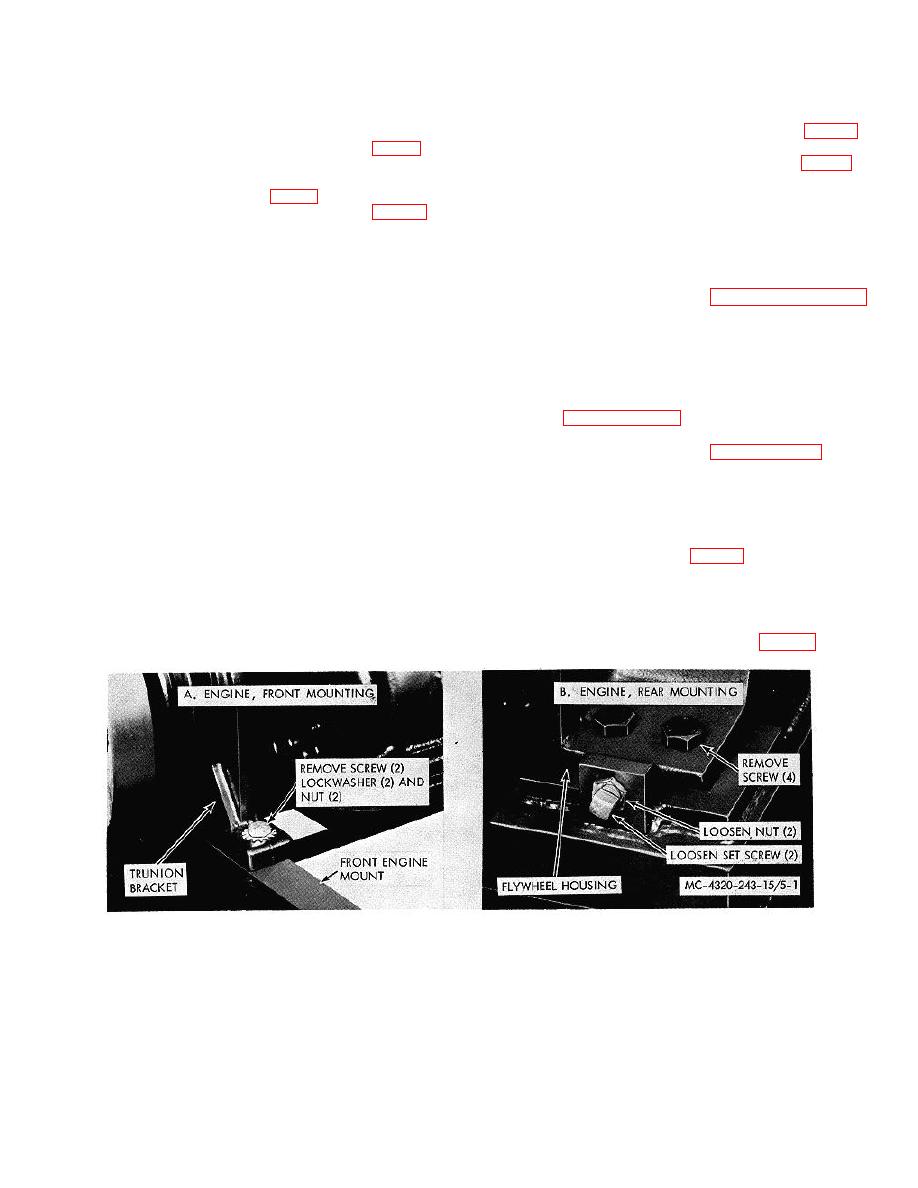
mounted d on a welded-steel skid. The front of the
engine is supported by a trunnion bracket which is
5-13. Engine a Remove the engine as follows:
bolted to an engine support mounted on the skid. The
rear of the engine is supported d by flywheel housing b
a. Remove the engine as follows:
bolted directly to the skid. The pump is secured to the
(1) Remove battery box (para b 511.
skid at the four corners of the pump bottom ease. The
(2) Remove muffler (fig 2-2).
engine is e connected to the pump by a flexible steel
(3) Disconnect gages and instruments fig. 3
grid that joins the engine coupling half to the pump
6).
coupling half. The engine and pump have b en aligned
(4) Remove housing assembly (para b 65)
at the factory and no further alignment is necessary
(5) Drain the radiator (para a-A i)
unless the engine or the pump is replaced.
(6) Disconnect radiator hoses (fig 7-7).
Figure 5-1. Engine, removal and installation.
5-2
|
|
Privacy Statement - Press Release - Copyright Information. - Contact Us |