 |
|||
|
|
|||
|
Page Title:
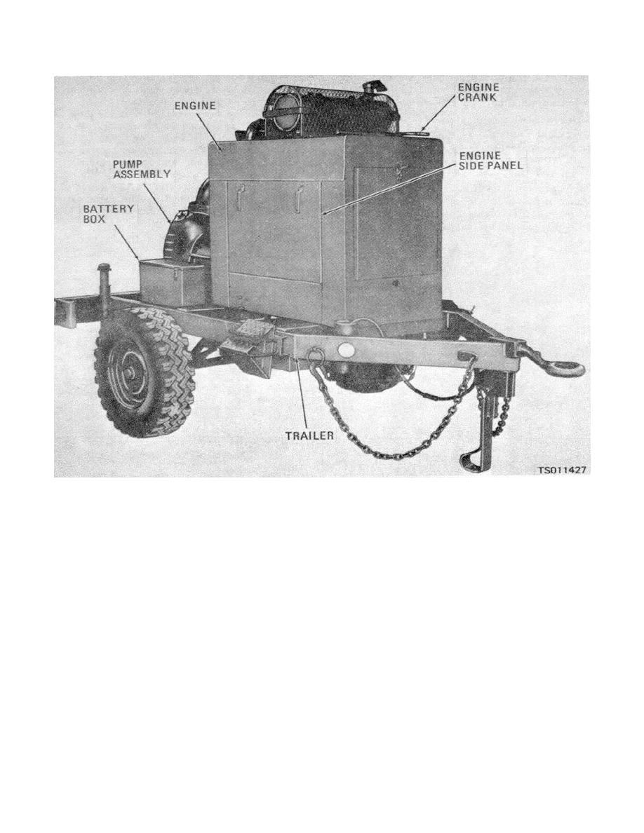
Figure 1-2. Centrifugal pump, right front view. |
|
||
| ||||||||||
|
|
 TM 5-4320-234-12
Figure 1-2. Centrifugal pump, right front view.
b. The centrifugal pump has a 6-inch suction
motor, has magneto ignition, and uses an alternator to
restore the charge of the battery as it is depleted by
flange secured to the front of the pump body and a 6-
operation of the starting motor. The conventional
inch discharge elbow secured to the top of the pump
radiator-type cooling system uses a pusher-type cooling
body. The bearing housing joins the flywheel housing of
fan which forces cooling air through the radiator from
the engine with the pump body, providing correct
the inside out. The fan also maintains a flow of air
spacing and proper alinement of the parts. The bearing
around the engine to provide proper cooling.
housing also provides the bearing seats for the ball
d. The engine and pump are protected by three
bearings that support the impeller shaft. The impeller is
keyed to the end of the impeller shaft and is secured
safety controls. The overspeed governor shuts off the
with a locking cone. The impeller is enclosed in a close-
engine when speed exceeds a preset maximum. The oil
fitting volute to provide efficient pumping operation. A
pressure safety switch shuts off the engine when oil
replaceable wear plate at the front of the impeller takes
pressure drops below a preset minimum.
The
most of the internal pump wear.
temperature safety switch shuts off the engine when
c. The engine is a six-cylinder, water-cooled,
coolant temperature exceeds a preset maximum.
e. The engine and pump are secured to a two-
pressure-lubricated, four-stroke-cycle, L-head type.
Engine speed is governed by a flyball-type governor.
wheeled chassis. The chassis consists primarily of hub
The engine is enclosed in a housing that has coolant
assemblies, pneumatic tires, welded frame, and axle.
and oil drains ported to the outside of the housing for
Two retractable stands are provided at the rear of the
easy access. The engine uses an electrical starting
chassis and one folding leg is installed at the front.
1-3
|
|
Privacy Statement - Press Release - Copyright Information. - Contact Us |
