|
| |
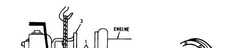
(5) Torque cap head screws (4) to 24 - 26 ft. lbs.
TM 5-4320-228-13&P
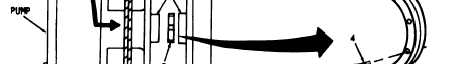
Figure 4-7 Pump alignment.
4-6.3.
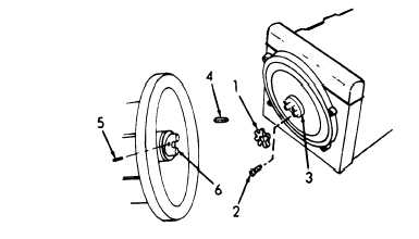
Coupling.
The rotational force of the engine is transferred to the centri-
fugal pump through a flexible coupling which joins the engine flywheel
and the pump shaft.
The coupling consists of a driving half which is
keyed to the pump shaft, and a resilient spider through which the tor-
que is transferred.
The resilience of the spider permits a free trans-
fer of torque even though slight misalignment may exist between the
driving parts.
a.
Removal.
(1) Remove centrifugal pump as per 4-6.2.
(2) Refer to figure 4-8. Remove spider (1). Remove cap
head screws (2), then remove drive half of coupling (3). Remove key
(4), set screws (5), then remove driven half of coupling (6).
Figure 4-8.
Flexible coupling, removal and installation.
4-15
|