|
| |
TM 5-4320-228-13&P
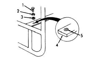
Figure 4-5.
Channel removal.
b.
Cleaning and Inspection.
Drycleaning solvent P-D-680, used to clean parts
is potentially dangerous to personnel and property.
Avoid inhalation of fumes and repeated or prolonged
skin exposure.
Wash exposed skin thoroughly with
soap and water.
Use in well ventilated area away
from open flame or excessive heat.
100°F (38°C).
Flash point is
(1) Clean channels and frame with approved cleaning solvent
or wire brush as required.
(2) Inspect channels and frame for cracks or bends.
(3) Inspect shock mounts for cracks, wear, and
deterioration.
c.
Installation.
(1) Refer to figure 4-5.
Repeat the removal procedure in
reverse sequence.
4-6.
CENTRIFUGAL PUMP.
The centrifugal pump is coupled to the engine with a flexible
coupling.
The pump case houses the impeller, wear plate, and seal and
serves as a water chamber with suction and discharge ports.
The
volute, which bolts to the front of the pump case, completely encircles
the impeller.
A check valve prevents water backflow through the pump.
The bearing housing mounts the pump bearings and shaft.
4-7
|