|
| |
APPENDIX A
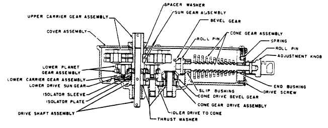
FIG. 20.
After adjustment is completed and the access cover
replaced, it should be sealed to prevent tampering or
unauthorized changing of the adjustment.
DISASSEMBLY
First remove the cover. Lift off the upper carrier gear,
sungear assembly, two lower planet gear assemblies,
lower driving sun gear, lower carrier gear assembly,
isolator sleeve, isolator plate and drive shaft assembly.
Next, drive out the roll pin and remove the adjustment
knob. Remove the adjustment plate drive screw,
adjustment plate and spring. This will allow the three
end bushings to be removed.
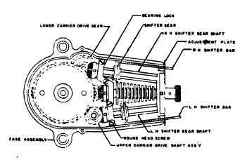
FIG. 21.
Next, remove the bearing lock and lift out the right and
left hand shifter assemblies and the cone drive gear
assembly. Remove the upper carrier drive shaft
assembly, lower carrier drive gear, cone drive bevel
gear, cone drive gear assembly and idler gear.
All parts showing excessive wear should be replaced. If
the case bushing is worn it is recommended that the
case assembly be replaced, rather " than the bushing,
as it is necessary to machine finish the bushings after
assembly to the case. See Parts List 3-C for
replacement part numbers.
Reassemble in reverse order of disassembly, with the
following precautions:
1. Add 14312 - 1 washers behind bevel gears until
ends of teeth line up and minimum backlash is
obtained.
2. Be sure the isolator plate key is engaged in the
keyway of the isolator sleeve and that the slot
engages the stop pin.
3. When assembling the two lower plane gears to the
lower carrier gear, note that each gear has a
center punch mark at one of the teeth. Point the
marked tooth of one gear at the drive shaft and
the other at a 900 angle to the drive shaft, Figure
21. This is necessary to allow the sun gear
assembly to mesh with the planet gears.
The "G" calibrator requires only a light coat of oil as all
gears have an electro-film coating which is self-
lubricating. Use S. A. E. 10 or lighter oil,.
PRINTED IN USA
A9-32
|