|
| |
TM 07661B-14-1
APPENDIX A
(13)
Install adjusting screw (1) along with locknut (2) in spring housing cap (3). Turn screw clockwise only until
resistance of springs is encountered.
c.
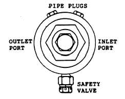
Adjustment. Adjust the dry chemical pressure regulator, using same procedure and specifications as per AFFF
pressure regulator, paragraph 3-29c. Refer to figure 3-19 for orientation of regulator ports.
Figure A 3-19. Dry Chemical Pressure Regulator
A 3-33. SHUTOFF VALVES. The two ball valves for dry chemical and AFFF shutoff are identical and are repaired by
following the same procedure.
a.
Disassembly. (figure 3-20)
(1)
Clamp valves body in a vise, valve stem up.
(2)
Note position of the coupling (1) for correct orientation at assembly. Remove locknut (2) and lift coupling
from valve stem.
(3)
Remove packing nut (3).
(4)
Remove two nuts (13) and body bolts (8) farthest from stem and loosen the other two bolts (8). Remove
valve body (12) from between the two adapters (7).
(5)
Remove seats (10) and body seals (9) and discard. Pull brass ball (11) from body.
(6)
Push valve stem (6) down into body cavity and remove from body bore.
(7)
Pull packing (4) from valve stem bore and discard.
(8)
Remove thrust washer (5) from valve stem.
b.
Assembly. (figure 3-20)
(1)
Install thrust washer (5) over threaded end of valve stem (6). Insert the valve stem through body cavity
into valve stem bore in body.
(2)
Insert brass ball (11) into body cavity, aligning ball groove with flats on bottom of valve stem. Rotate stem
as necessary to engage ball groove.
(3)
Install a new seat (10) on each side of ball, making sure the conical side is towards ball.
(4)
Install new body seals (9) over seats.
(5)
Position body (12) between the adapters (7) being sure alignment tabs rest on the two bolts. Insert body
bolts (8). Install nuts (13) and tighten evenly, making sure body adapters are seated firmly against body and body seals
are not pinched. Tighten nuts securely.
(6)
Carefully install new packing (4) over valve stem and push it down evenly to seat in valve stem bore.
(7)
Install packing nut (3) and tighten securely.
(8)
Install coupling (1) on valve stem and secure with locknut.
A 3-43
|