|
| |
TM 0766B-14/1
APPENDIX A
(4)
Install new diaphragm assembly (8) over slip ring and nozzle in body, centering it on the slip ring.
(5)
Put inner and outer adjusting springs (6, 7) on diaphragm backing plate. Put spring button (5) on top of
the two springs, convex side of button toward springs.
(6) Install housing cap (3) over assembled components in body, thread clockwise onto body and tighten
securely.
(7)
Install adjusting screw (1) and locknut (2) into spring housing cap. Turn screw clockwise only until spring
resistance is encountered.
c.
Adjustment. The nitrogen pressure regulator can be calibrated, or adjusted, using the following procedure:
(1)
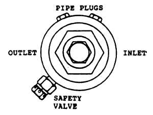
Leave pressure relief valve in one low pressure outlet port. Install one-quarter inch pipe plugs in other low
pressure port and high pressure port. See port orientation, top view of housing cap, figure 3-17.
Figure A 3-17 AFFF Pressure Regulator
(2)
Connect pressure regulator outlet to a test gage and a shutoff valve or control valve.
(3)
Connect regulator inlet to a controlled source of clean, dry compressed air or nitrogen capable of supplying
a minimum of 2000 psi pressure to the regulator inlet.
(4)
Turn the pressure adjusting screw (1, figure 3-16) clockwise until considerable resistance from spring
tension is encountered.
(5)
Open the shutoff or control valve a very small amount to allow a small flow through regulator.
(6)
Slowly open the valve to pressure source while observing test gage. Ensure that output pressure is not
exceeding 200 psi while increasing input pressure to 2000 psi.
(7)
Slowly turn regulator adjusting screw clockwise until test gage indicates 230 10 psi.
(8)
Alternately open and close flow control valve and observe that test gage pressure remains between 220
and 240 psi. Check for leakage. No leaks allowed. Tighten locknut and then recheck pressure setting.
(9)
Close pressure source valve and disconnect regulator from test set-up.
(10)
Install seal wire (19) to prevent tampering with setting.
(11)
Seal all regulator openings with plugs or tape and return unit to use or storage.
A 3-40
|

