|
| |
TM 07661B-14/1
APPENDIX A
b.
Installation.
(1)
Seal threads of fusible plug using instructions in NOTE, paragraph 3-14c.
(2)
Insert the plug into drain port of tank and tighten securely.
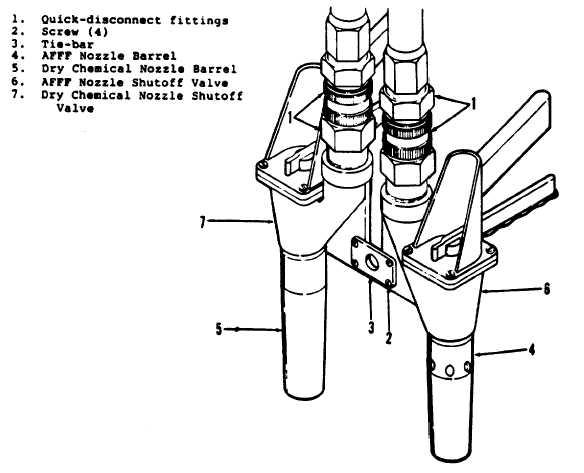
A 3-23. DISCHARGE NOZZLES. Removal procedures are identical for the two discharge nozzles.
a.
Removal. To remove either nozzle proceed as follows (figure 3-12):
(1)
Remove twin nozzle assembly from its bracket and disconnect it from the handline assembly by releasing
the quick disconnect fitting (1, figure 3-12).
(2)
Separate the two nozzles by removing the four screws (2) securing the tie bar (3) to the nozzles.
(3)
Using a suitable wrench unscrew the quick-disconnect fitting (1) from the nozzle.
(4)
If the nozzle is being replaced as a complete unit the removal is complete. If, however, only the shutoff
valve is being replaced, the nozzle barrel (4 or 5) must be removed.
(5)
All that is required to remove the nozzle barrel is to turn it counterclockwise.
Figure A 3-12. Discharge Nozzle Replacement
A 3-30
|