|
| |
APPENDIX A
TM 07661B-14/1
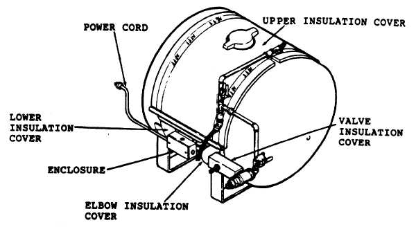
Figure A 2-2. Tank Heater Installation
shown in figure 2-3 to a power cord in an electrical enclosure. Power to the heaters is controlled by two thermostats
whose connections are also made in the enclosure. The thermostats are held against the tank side and are used to
sense agent temperature. The entire circumference of the tank is covered with an insulating blanket which is held in
place by a metal wrapper. The outlet tube, as well a as the shutoff valve, are also covered with insulation and a
protective wrapper.
b.
Heater Operation. The heater is wired at the factory to operate on 120VAC, 1 phase, 60 hertz power (figure
2-3). A 240VAC, 1 phase, 60 hertz power source may be used, providing the wire connections are changed from a
parallel circuit to a series circuit as shown in figure 2-3 and the plug is changed to an acceptable type.
When the temperature of the AFFF solution is above a nominal 75F both thermostat contacts are open and no current is
flowing through the circuit. When the temperature of the solution drops to a nominal 65F, the "high temperature"
thermostat closes, but since it is in series with the "low temperature" thermostat, there is still no current flow. When the
AFFF solution temperature within the tank falls to below a nominal 45F, the low temperature thermostat closes,
completing the electrical circuit.
Current flowing through the resistance wire of the heating elements heats the AFFF tank until the solution temperature is
raised to above a nominal 55F, at which point the low temperature thermostat again functions to open the circuit. If the
low temperature thermostat fails, the solution temperature will only rise to a nominal 75F where the high temperature
thermostat opens the electrical circuit. Thus the high temperature thermostat actually operates as a safety device.
A 2-4
|

