|
| |
TM 10-6630-247-13&P
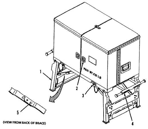
2-1. CABINET CONTROLS.
Leg Supports (1)
Two folding leg supports hold the cabinet at operating height and provide a stable platform for the
—
cabinet. Extensions on each leg allow the cabinet to be leveled when operating on an uneven surface.
Door Lock (2)
The door lock is located on the right cabinet door and is used to secure the cabinet doors in the closed
position.
Quick Release Pins (3)
Two quick release pins secure the leg supports up against the cabinet base when legs are folded,
Depressing button on top of pin releases internal ball locks permitting removal of pin.
Lift Handles (4)
Two stowable lift handles are located under the cabinet frame. When the cabinet is being lifted or
moved by personnel, the handles are extended to provided additional lifting capability. When not in
use, the handles are pushed back into the stowed position.
Brace Releases (5)
A brace release is located on each leg brace. Depressing the brace release unlocks the brace and
permits folding of the leg brace and leg support.
Figure 2-1. Cabinet Controls and Indicators.
2-2
|