 |
|||
|
|
|||
|
Page Title:
Installation of Filler/Discharge Hose Assembly and Filler/Discharge Valve Assembly |
|
||
| ||||||||||
|
|
 TM 10-5430-238-12&P
0005 00
Installation of Filler/Discharge Hose Assembly and Filler/Discharge Valve Assembly
2
3
8
7
6
5
4
1
4
NOTE
The filler and discharge hose assembly is fitted with a quick-disconnect female
coupling on one end and a quick-disconnect male adapter on the other end.
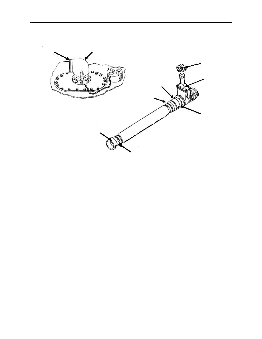
1. Place female coupling (1) on male adapter (2) end of filler/discharge elbow (3).
2. Push coupling cam-lever arms (4) into position to lock the hose assembly in place.
3. Place male adapter (5) end of the hose into female coupling (6) of the gate or butterfly valve (7).
4. Push coupling cam-lever arms (4) into position to lock the hose assembly in place.
5. Ensure gate or butterfly valve (7) is closed, rotating handle (8) to the right until it stops.
Valves
1. Gate valve (1) is fully opened by rotating hand-wheel (2) to the left, and backing off one-quarter turn.
2. Gate valve (1) is fully closed by rotating hand-wheel (2) to the right and backing off one-quarter turn.
Note the difference in exposure of the handle stem between the closed and open positions.
3. Ensure butterfly valve (3) (Models BA91-141 and BA91-140) is closed. Press down on the end of the
handle (4) to release the locking pin and turn until handle (4) is 90 to the valve body and stops.
Release handle (4).
4. Butterfly valve (3) is fully opened by pressing down on the end of handle (4) and turning it counter
clockwise to a parallel position in line with the valve body or hose assembly.
0005 00-12
|
|
Privacy Statement - Press Release - Copyright Information. - Contact Us |