|
| |
TM 10-4930-250-13&P
Section I. DESCRIPTIONAND USEOF
OPERATOR'S CONTROLS AND INDICATORS
1
2
3
4
/
5
/
2
0
FAULTS
ENGINE
INTAKE
ENGINE
ALTNTR
HEATER
HOT
START
ON
RUN
EMERGENCYSTOP
6
STOP
FF
PANEL LIGHTS
FAULT
LOW OIL
PUMPAGE
TURN
.,,CZZZ@@
LIGHTS
PRESSURE
HOT
TO
ON
RELEASE
0-0
PUSH TO STOP
OUT,
12
CIRCUIT BREAKERS
7
SYSTEM
AUXPUMP
5
0
0
8
INTAK
HEATE@@
2
2
10
9
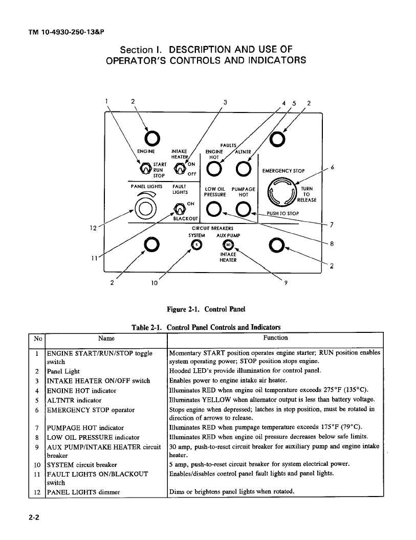
Figure 2-1. Control Panel
Table 2-1. Control Panel Controls and Indicators
No
Name
Function
1
ENGINE START/RUN/STOP
toggle
Momentary START position operates engine starter; RUN position enables
switch
system operating power; STOP position stops engine.
2
Panel Light
Hooded LED's provide illumination for control panel.
3
INTAKE HEATER ON/OFF switch
Enables power to engine intake air heater.
4
ENGINE HOT indicator
Illuminates RED when engine oil temperature exceeds 275*F (135*C).
5
ALTNTR
indicator
Illuminates YELLOW
when alternator output is less than battery voltage.
6
EMERGENCY
STOP operator
Stops engine when depressed; latches in stop position, must be rotated in
direction of arrows to release.
7
PUMPAGE HOT indicator
Illuminates RED when pumpage temperature exceeds 175*F (79*C).
8
LOW OIL PRESSURE indicator
Illuminates RED when engine oil pressure decreases below safe limits.
9
AUX PUMP/INTAKE
HEATER circuit
30 amp, push-to-reset circuit breaker for auxiliary pump and engine intake
FA
ULTS
E/N
GITTE
A LTIN
/T/R
R_
C@Ho
00
0
0
breaker
heater.
10
SYSTEM circuit breaker
5 amp, push-to-reset circuit breaker for system electrical power.
11
FAULT LIGHTS ON/BLACKOUT
Enables/disables control panel fault lights and panel lights.
s switch
12
PANEL LIGHTS dimmer
Dims or brightens panel lights when rotated.
2-2
|

