|
| |
TM 10-4930-247-13&P
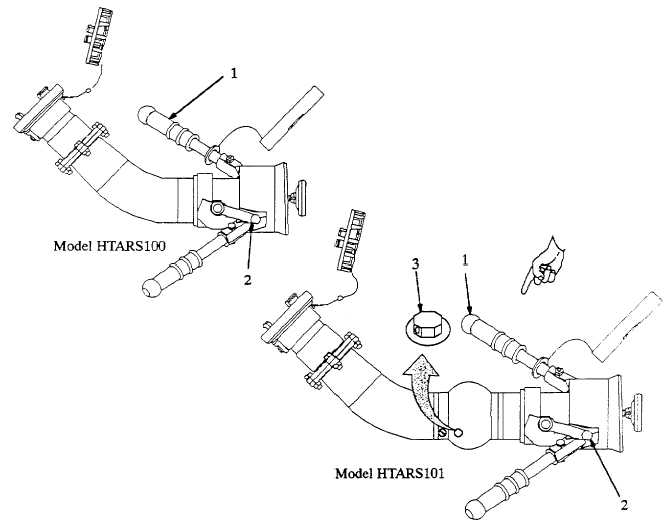
2-1. SINGLE POINT REFUELING NOZZLE (D1).
Refer to figure 2-1.
Locking Handles (1).
Two locking handles on the nozzle body aid positioning and connection of the nozzle to the aircraft refueling
adapter. The handles are turned to the right to connect the nozzle; left to disconnect.
Control Lever (2).
The control lever has two positions, OPEN and CLOSE. When the nozzle is connected to the aircraft refueling
adapter, rotating the crank handle to OPEN allows fuel flow through the nozzle. When set to CLOSE, fuel flow is
stopped. Mechanical locks prevent setting the crank handle to OPEN when the nozzle is not connected or
disconnecting the nozzle before the lever is set to CLOSE.
(Model HTARS101) Breather (3).
Allows ambient air pressure to enter regulator valve. Excessive leakage from vent indicates worn or damaged
internal components.
Figure 2-1. Single Point Refueling Nozzle (D1) Controls.
2-2 Change 4
|