Order this information in Print

Order this information on CD-ROM

Download in PDF Format


Click here to make tpub.com your Home Page

Page Title: Figure 4-19. Ball Valve Assembly Repair.
Back | Up | Next

Click here for a printable version

Google


Web
www.tpub.com

Home


Information Categories
.... Administration
Advancement
Aerographer
Automotive
Aviation
Combat
Construction
Diving
Draftsman
Engineering
Electronics
Food and Cooking
Math
Medical
Music
Nuclear Fundamentals
Photography
Religion
USMC
   
Products
  Educational CD-ROM's
Printed Manuals
Downloadable Books


TM 10-4930-247-13&P 4-22. BALL VALVE ASSEMBLY REPAIR -cont. e. 
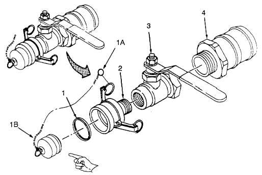
Assembly.  Refer to figure 4-19. (1) Apply anti-seize tape to male threads of female coupling (2) and adapter (4). (2) Install ball valve (3) on adapter (4). (3) Install female coupling (2) on ball valve (3). NOTE Make sure gasket is fully seated in groove of female coupling. (4) Install gasket (1) in female coupling (2). (5) Remove body of ball valve (3) from vise. (5A)  (Model HTARS101) Install retaining ring (1A) and dust plug (1B) on female coupling (2). (6) Install ball valve  assembly on fuel hose (para 4-21). NOTE: RING (1A) AND PLUG (1B) USED ON MODEL HTARS 101 ONLY. Figure 4-19.  Ball Valve Assembly Repair. Change 4  4-49

Privacy Statement - Press Release - Copyright Information. - Contact Us - Support Integrated Publishing

Integrated Publishing, Inc. - A (SDVOSB) Service Disabled Veteran Owned Small Business