|
| |
TM 10-4930-247-13&P
4-18.
VALVED DRY BREAK COUPLING REPAIR -cont.
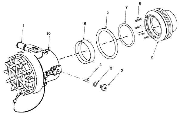
Figure 4-9. Valved Dry Break Coupling Removal.
b.
Disassembly. Refer to figure 4-10.
NOTE
Ensure that all parts identified as mandatory replacement parts are discarded and
replaced with new components.
(1)
Disconnect dust cap (2) from body (21).
(2)
Remove seal (1) from dust cap (2).
(3)
Remove bumper 13) and seal (4) from body (21).
(4)
Remove two self-locking screws (5) from arm (9). Remove arm and attached parts from body (21).
(5)
Remove screw (6), grip (8) and spring (7) from arm (9).
4-31
|