|
| |
TM 10-4930-245-13&P
2-2. LOCATION AND USE OF CONTROL AND INDICATORS - continued.
a.
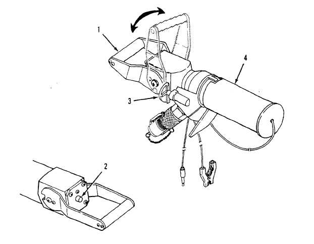
Handle (1) - Opens or closes the nozzle flow control valve. Handle shown in the closed position.
b.
Flow Indicator (2) - When visible, red indicator shows that nozzle discharge flow is stopped.
c.
Latch (3) - Holds nozzle handle in closed position. Latch must be pressed to release for changing position.
d.
Quick-disconnect automatic shutoff coupler (4) - Connects to vehicle fuel servicing adapter.
Change 3
2-2.1/(2-2.2 Blank)
|

