|
| |
TM 10-4930-238-12&P
2-7. ASSEMBLY AND PREPARATION FOR USE - Continued.
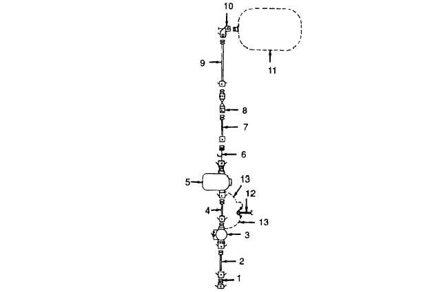
d. Installation for Filling a 500 G
allon Drum (1892.5 Liters). (Refer to Figure 2-5)
(1) Position pumping assembly (3) in its desired location.
(2) Position filter separator (5) in its desired location.
(3)
(4)
(5)
(6)
Figure 2-5. Piping Diagram for Filling Operation.
NOTE
Remove dust plugs and dust caps before installing individual components.
Connect adapter (1) to fuel source.
NOTE
Secure individual components with their camlock levers.
Connect suction hose assembly (2) to adapter and pumping assembly (3) inlet connection.
Connect suction hose assembly (4) to pumping assembly (3) discharge connector and filter
separator (5) inlet connector.
Connect adapter water detector (6) to filter separator(S) outlet connection. Connect suction
hose assembly (7) to adapter water detector (7) and pressure control valve (8).
NOTE
Refer to TM 10-8110-201-14&P for maintenance of the fuel drum and
pressure control valve.
Change 1
2-13
|