|
| |
TM 10-4320-351-14
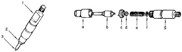
a. Retaining Nut
d. Rod
b. Nozzle
e. Spring
c. Distance Ring with
f.
Adjusting Shim
Locating Pin
g. Injector Casing
Figure 6-43. Fuel Injector Nozzle Cleaning
6.4.20 Install Fuel Injector. (Refer to figure 6-44.)
This task consists of:
a. Installation
INITIAL SET-UP:
Tools:
Materials/Parts Required:
Ratchet Wrench, 3/8 in. Drive
Washer (Appendix I, Item 34)
(Appendix B, Section III, Item 3)
Washer (Appendix I, Item 36)
Socket, Socket Wrench, 13 mm
Washer (Appendix I, Item 39)
(Appendix B, Section III, Item 3)
Combination Wrench, 10 mm
(Appendix B, Section III, Item 3)
Combination Wrench, 17 mm
(Appendix B, Section III, Item 3)
Equipment Condition:
Fuel injectors cleaned (para. 6.4.19)
Cylinder head installed (para. 6.4.13)
NOTE
Copper washers (1) under fuel injectors are used to adjust injector protrusion into
the combustion chamber of cylinder head. If the old fuel injector is being installed,
ensure number of washers are the same number that were removed. If a new fuel
injector is to be installed measure the nozzle length of the old and new injectors,
remove or insert copper washers to adjust the protrusion of the new injector in the
cylinder head to achieve the same protrusion as with the old injector.
a.
Insert copper washer(s) (1) in cylinder head.
b.
Install and tighten union bolt (2), union (3) and copper washers (4 and 5).
c.
Position fuel injector (6) in cylinder head.
6-70
|