|
| |
TM 10-4320-351-14
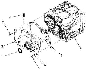
Figure 6-34. Timing Cover Installation
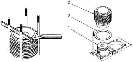
Figure 6-35. Piston Protrusion Check
b.
Using a feeler gauge and a machinist's rule (or other straight edge) as illustrated below, verify piston (1) is above
top of cylinder (2) by 0.004 to 0.008 in. (0.1-0.2 mm). If measurement is within this range, piston (1) protrusion is
satisfactory. If reading is less than 0.004 in. (0.1 mm) above top of cylinder (2), gaskets (3) must be added
between cylinder and crankcase. If reading is more than 0.008 in. (0.2 mm) above top of cylinder (2), gaskets (3)
must be removed between cylinder and crankcase.
NOTE
When adding or removing cylinder gaskets (3), measure thickness of gasket(s) to
ensure proper range will be attained.
c.
Remove cylinder (1) from piston (2). Add or remove gaskets (3) as required to obtain piston (1) protrusion of
0.004 to 0.008 in. (0.1-0.2 mm).
d.
Refer to paragraph 6.4.6 for cylinder installation.
6-56
|