|
| |
TM 10-4320-351-14
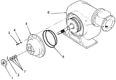
Figure 5-5. Vane Pump Housing O-Ring Replacement
(2)
Install vane pump housing (5).
(a)
Hold vane pump housing (5) over shaft so that mounting holes and guide pin holes are aligned, and
install three 1/4" x 28 bolts through housing into mounting holes. Space the bolts approximately
equal distances apart and tighten finger tight. Using the bolts as guides, push the vane pump
housing onto the shaft. Remove the three guide bolts.
(b)
Apply anti-seize compound to and install the six socket head screws (3) and flat washers (4) to
secure the vane pump housing (5) to the impeller housing (6). Alternately tighten screw pairs to draw
housing down evenly. Rotate shaft by hand after each tightening sequence to ensure binding has not
occurred. When all six screws are finger tight, repeat pattern to secure tightly. Verify proper
alignment by rotating shaft by hand. Shaft will rotate freely without binding when all screws are
tightened evenly.
(3)
Install shims (7) on shaft.
5-14
|

