|
| |
TM 10-4320-348-14
SECTION I. DESCRIPTION AND USE OF OPERATOR’S CONTROLS AND INDICATORS
2.1 SCOPE. This section provides description and use of operator controls needed to operate the pumping assembly
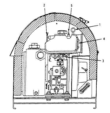
Figure 2-1. Operator’s View of Internal Controls and Indicators (Front Sound Enclosure Panel Removed).
2.2 OPERATOR’S CONTROLS AND INDICATORS.
Key
External Control or Indicator (See Figure 2-1)
Function
1
Air cleaner restriction indicator
Indicates blockage of air cleaner element. A red band appears in window
to indicate the need for replacement of the air cleaner element. The
indicator is threaded into the air cleaner housing and is activated by high
negative pressure. Indicator can be reset.
2
Decompression lever
Controls engine compression when starting (the engine turns over easier
when starting). Lever is depressed for starting and returns automatically on
the next piston compression cycle.
3
Fuel cock
Shutoff valve for diesel fuel.
4
Fuel gauge pipe
Sight gauge for diesel fuel level in fuel tank.
5
Cold weather plug
The engine is equipped with a rubber plug in the rocker arm cover to
facilitate the addition of a few drops of oil, which aid in cold weather
starting.
2-2
|