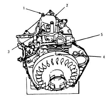
Order this information in Print

Order this information on CD-ROM

Download in PDF Format


Click here to make tpub.com your Home Page

Page Title: Figure 4-25. Alignment of Flywheel With Cylinder Block
Back | Up | Next

Click here for a printable version

Google


Web
www.tpub.com

Home


Information Categories
.... Administration
Advancement
Aerographer
Automotive
Aviation
Combat
Construction
Diving
Draftsman
Engineering
Electronics
Food and Cooking
Math
Medical
Music
Nuclear Fundamentals
Photography
Religion
USMC
   
Products
  Educational CD-ROM's
Printed Manuals
Downloadable Books


TM 10-4320-348-14 Figure 4-25.  Alignment of Flywheel With Cylinder Block Figure 4-26.  Adjusting Valve Clearance (7) Insert 0.006 inch (0.15 mm) feeler gauge between valve rocker arm and top of the valve spring cotter. (8) While  turning  the  adjusting  screw  clockwise,  slowly  slide  the  feeler  gauge  back  and  forth.    Stop  turning adjusting screw when slight resistance is felt on the feeler gauge. (9) Remove  feeler  gauge  and  tighten  locknut.    Keep  screwdriver  inserted  into  adjusting  screw  to  prevent adjusting screw from turning. 4-58

Privacy Statement - Press Release - Copyright Information. - Contact Us - Support Integrated Publishing

Integrated Publishing, Inc. - A (SDVOSB) Service Disabled Veteran Owned Small Business