|
| |
TM 10-4320-347-13&P
Section 1. DESCRIPTION AND USE OF
OPERATOR'S CONTROLS AND INDICATORS
2.1. INTRODUCTION . The pumping unit is designed for operation in a wide range of climatic conditions.
Operators must be aware of any peculiarities or operational limitations for their specific installation. Before
setting up and operating this system, be sure that you have determined the type of terrain and climate in which
you will use the unit and that you have assembled and serviced the system to match the existing needs.
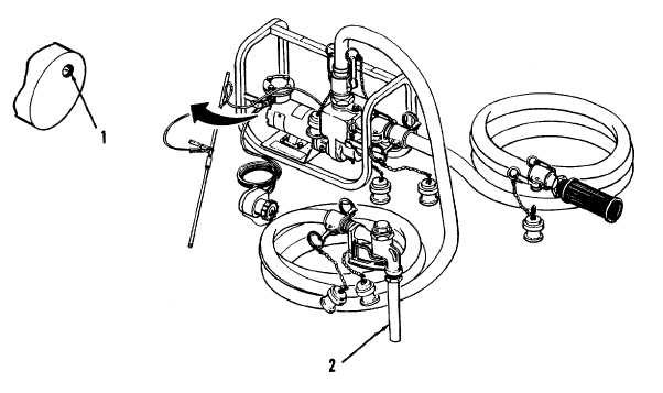
2.2. OPERATOR'S CONTROLS AND INDICATORS . For controls and indicators applicable to the pumping
unit, refer to the following descriptions and to Figure 2-1.
2.2.1. Pumping Assembly Control Switch (1). The control switch controls the electric motor by turning
it on and off.
WARNING
Personal injury may result if the motor is not turned off during service of maintenance.
2.2.2. Nozzle Assembly (2). When fuel is being pumped by the pumping unit, it is discharged by the
operator through the use of the nozzle assembly attached to the discharge end of the discharge hose.
Depressing the nozzle handle will allow fuel to flow from the spout of the nozzle. When the handle is released,
it will automatically retract to stop the flow of fuel from the spout of the nozzle. Figure 2-1. Operator's Controls
and Indicators.
Figure 2-1. Operator’s Control and Indicator
2-2
|

