|
| |
TM 10-4320-343-14
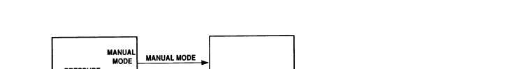
Figure 1-10.
Regulator Assembly Functional Block Diagram.
1.14.2.6.2 Pressure and Compound Gauge.
The compound gauge is connected to the suction
side and monitors flow of water into the pump assembly.
The pressure gage
monitors output pressure of the pump assembly.
1.14.2.7 Regulator Assembly.
The regulator assembly (figure 1-10) provides feedback
from the output of the pump.
This feedback controls the speed of the engine by
transmitting-electrical- signals to a magnetic pick-up and control box. It consists
of a pressure controller, control box, magnetic pickup and actuator.
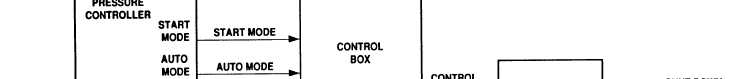
1.14.2.7.1 Pressure Controller.
The pressure controller provides a selection of
operating modes.
The mode switch provides three modes of operation.
The three
modes are START, MANUAL, and AUTO.
The pump is started in the start mode and then
put into either the AUTO or MANUAL mode.
Normally the operation mode is AUTO.
The
AUTO mode converts pump suction and discharge pressures to the electrical signals.
The electrical signals are transmitted to the magnetic pickup.
When discharge
pressure either exceeds or goes below 125 psi (8.7 kg/cm2, an electrical signal is
sent to the control box to reduce or increase the engine speed as required.
When
set to MANUAL mode, the engine speed is controlled manually.
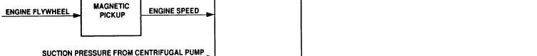
1.14.2.7.2 Magnetic Pick-up.
The magnetic pickup converts engine flywheel speed into
electrical pulses.
The engine flywheel speed provides actual engine speed.
The
electrical pulses are then sent to the control box.
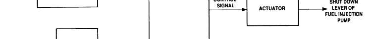
1.14.2.7.3 Control Box.
The control box receives the electronic signals and controls
the actuator output lever.
When the pressure is above 125 psi, the control box
causes the actuator to reduce the engine speed.
When the pressure falls below 125
psi, the control box causes the actuator to increase the engine speed.
1-21
|