|
| |
TM 10-4320-343-14
6.6.4 Engine Maintenance.
(continued)
Start by tightening middle bearing cap and those on either
side, finish with bearing caps at ends. The crankshaft
must be able to rotate freely.
e . Install bearing caps (7) and (6), with their identification number
f .
9“
h .
corresponding to and in same direction as
that stamped on crankcase.
I n s t a l l
washers (5) and bolts (4).
Torque in accordance with appendix G.
I n s t a l l p i s t o n s ( 3 ) .
Install connecting rod caps (2) and connecting rod bolts (1). Torque in
accordance to appendix G.
Assembly flywheel assembly as follows:
(1) If ring gear (figure 6-9, 12) has been removed,
heat new ring gear to a
temperature of 248° F (120°C) and position
it on flywheel (11) and tap it
into position so it seats against shoulder.
(2) Install flywheel (11) with bolts (10). Torque in accordance with
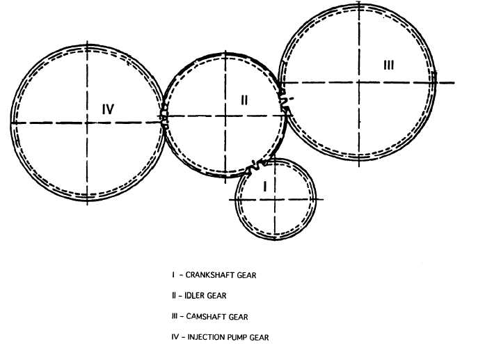
Figure 6-15. Timing Gears Layout with Match Marks
6-31
NOTE
appendix G.
|