|
| |
TM 10-4320-343-14
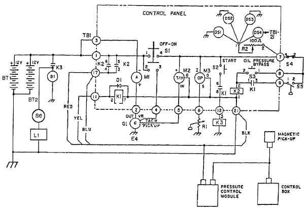
1.14.2.3.3.3. Light Circuits. The panel lights consist of the light switch (rheostat) R2 and four panel lights DS 1 through
DS4. When both S1 and R2 are on, current flows through each of the lamps, which are connected to the rheostat in
.parallel. The amount of current flow and thus the intensity of illumination can be controlled by varying the effective
resistance of the rheostat.
1.14.2.3.3.4. Charging Circuits. When the system is running and the alternator is operating correctly, current flows into
the batteries because the voltage produced by the alternator is slightly higher than the nominal voltage of the battery.
This current keeps the batteries charged and the ammeter indicates a charge rate.
1.14.2.3.3.5. Indicator Circuits. The electrical system provides three types of indicator circuits as follows:
a.
Oil Pressure Circuits. This circuit consists of oil sensor R1 and the pressure gauge (M3). Because R1 is
essentially a variable resistor that changes in value, based on the amount of oil pressure in the engine (high if oil pressure
is low and low if pressure is high), current flow through R1 and through the gauge will vary with the resistance of R1 and
will indicate low oil pressure if resistance is high and high oil pressure if resistance is low.
b.
Tachometer/Hourmeter (M2). The tachometer receives power when S1 is on and a signal from the alternator that
corresponds to rpm of the alternator. The hourmeter portion is active (registers elapsed time) when power is applied and
the tachometer converts the signal it receives from the alternator and changes it to a meter movement that represents
engine rpm.
Figure 1-4.1. Schematic Diagram for Model 350 PAFN (Sheet 1 of 2).
1-14.2 Change 1
|

