|
| |
TM 10-4320-343-14
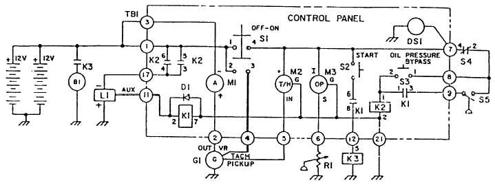
LIST OF COMPONENTS
REFRENCE DISIGNATION
DESCRIPTION
REFERENCE
DESIGNATION DESCRIPTION
B1
Starter Motor
M3
Oil Pressure Gauge
BT1 and BT2
Battery
R1
Oil Pressure Sending Unit
G1
Alternator
S1
Push-Pull Switch
K1
General Purpose Relay
S2 and S3
Pushbutton Switch
K2
Power Relay
S4
V-belt Switch
K3
Starter Relay
S5
Low Oil Pressure Switch
L1
Fuel Shutoff Solenoid
TB1
Terminal Board
M1
Ammeter
D1
Silicone Diode
M2
Tachometer/ Hourmeter
DS1
Panel Light
Figure 1-3. Schematic Diagram for Non-regulated Models.
1-12
|