|
| |
TM 10-4320-342-24
4-4. STARTER-GENERATOR REPAIR - continued.
Refer to 4-18.
(38)
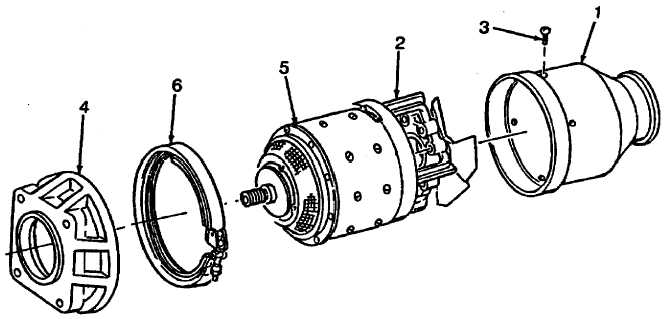
Position air inlet (1) on end bell assembly (2) and install screws (3).
(39)
Position adapter (4) on drive end bell (5) and secure with clamp (6).
Figure 4-18. Air Inlet and Adapter Installation
f.
TEST AFTER ASSEMBLY.
(1)
Test Equipment.
(a)
Test equipment shall include a variable speed test stand capable of driving the starter-generator at speeds
of 7,000 to 12,000 rpm at rated load, and 13,000 rpm at no load.
(b)
The test stand shall be equipped with suitable instrumentation to measure torque, speed, voltage, current
and temperature. Adequate circuitry must also be provided to load the generator. Refer to Figure 4-19 for
starter-generator electrical connections and Figure 4-20 for typical test setup.
4-23
|