|
| |
TM 10-4320-324-14
6-7. Engine Assembly Repair (CONT).
(7)
Check locating pin in crankshaft gearwheel. It should project 0.67 inch (17 mm) from side opposite that bearing
identification mark. If necessary, install a new locating pin.
(8)
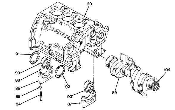
Install crankshaft gearwheel (104) with face bearing identification mark directed away from crankshaft.
(9)
Install bearing halves (90) in crankcase (20) and bearing caps (86 and 87), making sure that identification marks
are correct.
(10) Coat ring stop (91 and 92) halves with grease and stick them by their smooth faces to first bearing web and first
bearing cap.
(11) Install eight dowel bushings (88).
(12) Using oil, lubricate crankshaft journals and install crankshaft (89) with crankshaft gear match mark positioned.
(13) Ensure bearing shells are seated in main bearing caps and bearing webs.
NOTE
Start by tightening middle bearing cap and those on either side, finish with bearing caps at ends. The
crankshaft must be able to rotate freely.
(14) Install bearing caps (86 and 87), with their identification number corresponding to and in same direction as that
stamped on crankcase (20). Install flat washers (85) and bolts (84). Preload bolts (84) to 22 lb-ft (30 N
m).
Stage 1 angle is 60°. Stage 2 angle is 45°. Total is 105°.
6-24
|

