|
| |
TM 10-4320-324-14
NOTE
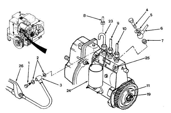
No. 1 injection pump outlet is located at governor end on injection pump.
(11)
Install special overflow pipe (23) and catch container (24) onto No. 1 injection pump outlet, and loosely install
two remaining injection lines (9 and 10).
(12)
Rotate governor input lever (27) clockwise (towards dipstick), to full run position, and secure lever in position.
(13)
Install plug (25) in overflow port.
(14)
Install high pressure hand pump (26) to inlet port with two new washers (2) andbanjo bolt (1).
(15)
Adjust start of fuel injection as follows:
(a)
Turn crankshaft counterclockwise, through 90 degrees from point of fuel mark (FI). Rotate V-belt pulley
clockwise until FI mark registers with timing indicator.
(b)
Pump hand-pump (26) until fuel flows from overflow tube (23).
5-35
|