|
| |
TM 10-4320-324-14
CHAPTER 2
OPERATING INSTRUCTIONS
Para
Contents
Page
2-5
Assembly and Preparation for Use ........................................................................................................
2-9
2-2
Controls and Indicators .........................................................................................................................
2-1
2-12
Emergency Procedures .........................................................................................................................
2-22
2-11
Fording or Swimming ............................................................................................................................
2-22
2-6
Initial Adjustments and Daily Checks .....................................................................................................
2-12
2-1
Introduction (Controls and Indicators) ....................................................................................................
2-1
2-3
Introduction (PMCS) ..............................................................................................................................
2-2
2-9
Nuclear, Biological, and Chemical (NBC) Decontamination ...................................................................
2-19
2-7
Operating Procedures ...........................................................................................................................
2-12
2-10
Operation in Unusual Weather ..............................................................................................................
2-20
2-4
PMCS Procedures .................................................................................................................................
2-6
2-8
Preparation for Movement .....................................................................................................................
2-19
Section I. DESCRIPTION AND USE OF OPERATOR'S CONTROLS AND INDICATORS
2-1. Introduction.
This section describes the different controls and indicators used to operate the pumping assembly.
2-2. Controls and Indicators.
NOTE
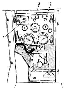
The control panel is located on the forward left side of the
pumping assembly.
a.
Start/Stop. This switch (1) is a push-pull type switch and is marked
EMERGENCY STOP, PULL TO START, PUSH TO STOP. The
switch is pulled out during engine start cycle and remains pulled out
while engine is operating. It is pushed in to shut down engine.
b.
Start Switch. This switch (2) is a pushbutton type switch and is
marked START. This switch is pushed in and held during engine
start to activate K3 start relay. The switch is released upon ignition.
c.
Oil Pressure Bypass Switch. This switch (3) is a pushbutton type
switch and is marked OIL PRESSURE BYPASS. The switch must be
pushed in simultaneously with start switch during engine start. The
oil pressure bypass switch is released upon ignition and buildup of oil
pressure to 10 PSI.
2-1
|

