|
| |
TM 10-4320-324-14
(k)
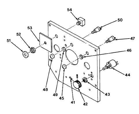
Remove two set screws (41), knob (42), nut (43), and rheostat (44).
(1) Remove rubber knob (45), nut (46), and start switch (47).
(m) Remove rubber knob (48), nut (49), and oil bypass switch (50).
(n) Remove round nut (51), button (52), plate (53), and emergency stop switch (54).
c.
Repair. Repair of the control panel assembly consists of removing and replacing electrical components and
gauges. When repairing solder joints, wire connections must be made mechanically sound before they are
soldered; solder alone does not provide sufficient strength to prevent breakage. Surfaces of connections to be
soldered must be clean and bright. Solder should be a lead-tin solder conforming to Specification QQ-S-571E.
Wires should always be heated to the point at which the solder will melt completely and flow into all parts of the
joint. Excessive buildup of solder globs on the joint should be avoided or removed.
4-183
|