|
| |
TM 10-4320-311-14
1-12. General. This section contains essential information which the operator must know to operate the pumping unit
safely and efficiently. The section is broken down into subsections that address the operation or use of the pumping
unit's major components. Paragraph 1-11.a, above, illustrates and identifies all of the components that combine to make
up the pumping unit
1-13. Storage Chests 1 and 2 and Pump Accessories Paragraphs 1-11.c and 1-11.d, above, illustrate and identify the
contents of each storage chest. The use of the various pump accessories provide many possible connection
combinations to accommodate all flammable liquid transfer and dispensing requirements The name of each accessory
and its appearance identify its function.
1-14. Pump Assembly. The major components of the pump assembly are described in paragraph 1-11.b, above.
Additionally, the controls and Indicators needed to safely and efficiently operate the pump assembly are described in
detail in Chapter 3.
a.
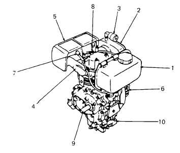
Diesel Engine Major Components (See Figure 1-5).
(1)
Diesel engine fuel system
(a)
A fuel tank (1) is attached to the engine to provide fuel during operation.
(b)
A three-way valve is mounted on the sound enclosure front panel. This valve can be used to select
an external fuel source for the engine during prolonged operation. A detailed description of this
valve and external fuel connections is provided in Chapter 2.
Figure 1-5. Diesel Engine, Major Components and Principles of Operation
1-11
|

