|
| |
TM 10-4320-307-10
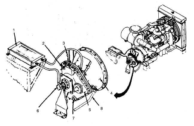
1-15 SPEED INCREASER WITH CLUTCH.
a.
Operation. The pump shaft is connected to the engine by the speed increaser. The output shaft of the
speed increaser gear box is coupled to the pump shaft using a flexible coupling. The gear box takes its input
from the splined shaft of the clutch. The clutch power ring is flange-mounted to the engine flywheel. When the
clutch is engaged, power is transmitted from the engine flywheel to the pump shaft allowing optimum pump
speed to be attained using optimum engine speed.
b.
Description.
HEAT EXCHANGER (1). Oil to air heat exchanger.
OIL FILL INLET (2). Inlet for adding lubricating oil to gear box.
DIPSTICK (3). Allows measurement of oil level in gear box oil sump.
POWER TAKEOFF (4). Houses a two-plate clutch that mates the engine flywheel to the gear box.
GEAR BOX (5). Houses one-stage step up gears and bearings.
GEAR LUBE OIL PUMP (6). Circulates lubrication oil from the gear box through a heat exchanger for cooling.
OIL DRAIN PLUG (7). Outlet for removing lubricating oil from gear box.
CLUTCH OPERATING LEVER (8). When engaged, the speed increasing gear transmits power from the
engine flywheel to the pump shaft, matching optimum engine speed to optimum pump speed.
1-18
|

