|
| |
TM 10-3835-231-13
2-6. OPERATING PROCEDURES. - continued
e.
Sample Points.
Normally, the quality of product shipped to the TPT has been proven at the, source and again upon arrival at the point
where it is pumped to the associated pipeline feeding the TPT. Facilities at the TPT permit sample taking as follows:
(1)
A sampling assembly (See figure 1-4) is installed in the header feeding the TPT switching manifold from the
associated pipeline or other delivery system. The primary use of the sampling assembly is to check incoming fuel and
establish the arrival of different specification fuel. It can also be used to spot sample and check the quality of incoming
fuel.
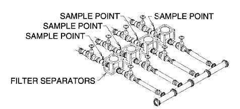
(2)
A sample point is located in the discharge line of each filter separator. The primary purpose of this sample
point is to check the quality and make sure no water is carried over to the dispensing assembly.
Figure 2-18. Fuel Sampling Points at Filter Separators
(3)
There are no built in facilities to take composite samples from the fabric collapsible tanks. A bottom sample
may be taken from the drain connection to check the accumulation of bottom sediment and water (BS & W).
2-42
|