|
| |
TM 10-3835-231-13
4-36. REMOVAL AND INSTALLATION OF COMPONENTS WVITH DOUBLE GROOVE CONNECTION FITTINGS.
This task covers:
a. Removal
b. Installation
INITIAL SETUP
Material/Parts
Equipment Condition
Rags (Appendix E, Item 4).
System de-pressurized and drained. (See para 4-34.)
Petrolatum (Appendix E, Item 5).
This paragraph applies to the following components:
6 inch x 50 ft Hose Assembly
6 inch Gate Valve Assembly
6 inch x 500 ft Hose Assembly
6 inch Ball Valve Assembly
Fuel Sampling Assembly
Pressure Regulating Valve Assembly
6 inch x 12 ft Hose Assembly
Female Coupling Adapter Assembly (6 inch)
Female Coupling Adapter Assembly (4 inch)
6 inch Pressure Control Valve Assembly
Male Coupling Adapter Assembly (6 inch)
Meter Skid Assembly
WARNING
FUEL SPILLS
Spills can result in saturated soil and cause a potential fire hazard.
a.
Removal.
(1)
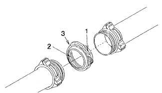
Release coupling handle (1).
(2)
Carefully pull fittings apart.
Figure 4-19. Double Groove Connection Fittings
4-60
|