|
| |
TM 9-2330-398-24
4-1.
ENGINE ASSEMBLY REPAIR (continued).
38.
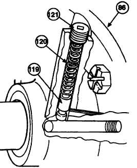
Remove recessed plug (121) from rear bearing
plate (86).
39.
Remove bypass spring (120) and valve plunger
(119) from rear bearing plate (86).
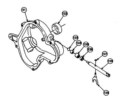
40.
Remove external retaining ring (127) securing
governor yoke (129) to governor shaft (128), and
remove governor yoke (129) from governor shaft
(128).
41.
Remove governor shaft (128) from gear cover
(51).
NOTE
Do
not
remove
pressed-in
components, such as bearings,
seals, and plugs, unless there is
evidence of damage, excessive
wear, or looseness.
42.
Place gear cover (51) on wooden supports and
drive out seal (121). Discard seal.
43.
Using valve guide driver tool, driveout needle bearing (124) and seal (126) from gear cover (51). Discard seal.
44.
Remove thrust bearing (124) and ball (123) from gear cover (51).
4-12
|