|
| |
TM 9-2350-398-24
2-135. G, R, P, and-M VALVE ASSEMBUES REPLACEMENT.
This Task Covers:
a. Removal b. Installation
Initial Setup:
Tools/Test Equipment:
Equipment Conditions:
•
General mechanic's tool kit (Item 4,
•
Semitrailer uncoupled (refer to TM 9-2330-398-10).
Appendix B)
•
Tank drained and purged (refer to TM 9-2330-398-10).
Material/Parts:
• Self-locking nut (16) (Item 171, Appendix F)
NOTE
•
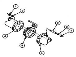
Removal and installation of G and M valve assemblies are the same. One valve assembly is shown.
• R and P valve assemblies are secured with screws and self-locking nuts.
a.
REMOVAL
1.
Remove 16 self-locking nuts (1) and eight studs (3) from valve (5) and two flanges (4). Discard self-locking nuts.
2.
Remove valve (5) from two flanges (4).
b.
INSTALLATION
Install valve (5) on two flanges (4) with eight
studs (3) and 16 washers (2) and new self-
locking nuts (1).,
FOLLOW-ON MAINTENANCE:
•
None
2-296
|